Difference Between Sheet Metal Design And Generative Sheet Metal Design
Catia Sheetmetal Bend Tables Explained Inceptra

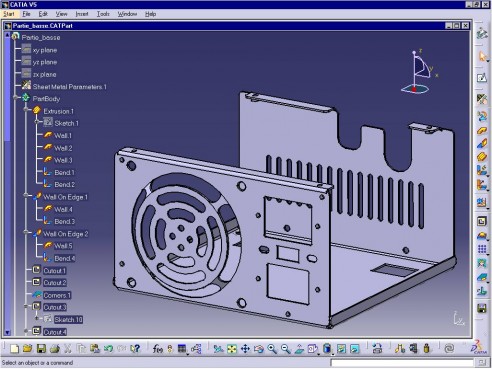
Advanced Catia Sheetmetal Grabcad Tutorials

Generative Sheet Metal Design Catia I Assignment 1 I Part 1 Youtube

Catia V5 Mechanical Product Design

Generative Sheet Metal Design Catia I Assignment 1 I Part 3 Youtube

Catia V5 Sheet Metal Practice Design 1 For Beginners Catia Practice Cad Designs Youtube
Recommended minimum distance between hole slot edge to bend in sheet metal design is three times the sheet thickness plus bend radius.
Difference between sheet metal design and generative sheet metal design.

Catia V5 V6 Tutorial Sheet Metal Design Tutorial Part 02 Design Tutorials Metal Design Tutorial

Catia V5 V6 Tutorial Sheet Metal Design And Manufacturing In Detail Sheet Metal Metal Design Sheet

Catia V5 Tata Technologies Plm Solutions

Solidworks Sheet Metal Tutorial Switch Box Youtube Sheet Metal Drawing Solidworks Tutorial Sheet Metal
Source : pinterest.com
